
Weldline Strength
Calculate the strength of a material at its weldline
While we’ve strived to predict material-performance as accurate and reliable as possible, actual performance may differ. Don’t hesitate to contact us for verification of outcomes. Akulon®, Arnite®, Arnitel®, Durethan®, EcoPaXX®, ForTii®, Novamid®, Pocan®, Stanyl®, Tepex® and Xytron™ are trademarks of Envalior. All information supplied by or on behalf of Envalior in relation to its products, whether in the nature of data, recommendations or otherwise, is supported by research and, in good faith, believed reliable, but Envalior assumes no liability and makes no warranties of any kind, express or implied, including, but not limited to, those of title, merchantability, fitness for a particular purpose or non-infringement or any warranty arising from a course of dealing, usage, or trade practice whatsoever in respect of application, processing or use made of the aforementioned information, or product. The user assumes all responsibility for the use of all information provided and shall verify quality and other properties or any consequences from the use of all such information. Typical values are indicative only and are not to be construed as being binding specifications. Colorants in the product or other additives may cause significant variations in typical values.
Tool info
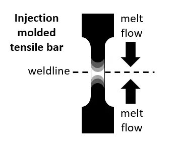
During injection molding the part geometry and obstacles to the melt flow may cause the melt to separate and rejoin. In that location a weldline (or meltline) will be formed, potentially impairing the mechanical properties of the final part. Understanding part design, mold design, processing conditions can help to avoid problems and improve the part esthetics.


Design Solutions
Weldlines occur in almost all injection molded parts and can potentially form weak spots. However, in many cases this risk can be mitigated by a proper a priori part design or mold design.
Mold filling simulation
By moving the gate and, if possible, by changing the wall thicknesses, the path of the polymer melt in the cavity and thus the position of the weld line can be influenced. Since this is associated with changes to the mold, the effectiveness of the measure should be checked by first carrying out a Mold filling simulation.
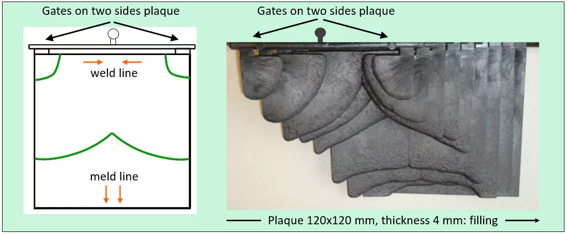
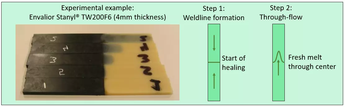
The schematic on the right shows a schematic and experimental result of injection molding a plaque with the intent to create both a weldline and a meldline.
Venting location
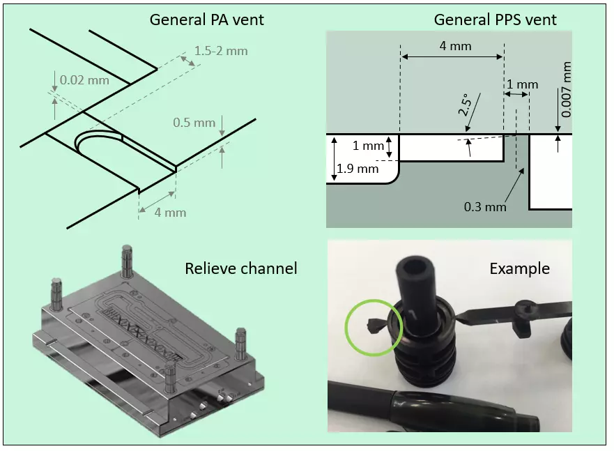
Validate venting location to avoid air entrapment at the weldline location.
- Add/change the venting location if needed.
- Improve the venting in the affected areas of the mold to help filling.
- Make sure venting dimensions are adequate for the part and plastic used.
Number of gates
Make a conscious choice between single-point or multi-point gating. Potentially, move gate to improve flow conditions. An additional aspect to consider is to control timing of the gates.
With one gate the tool design is easiest, but the operating freedom is very limited. Having multiple gates does not only change the melt flow, but also allows for variation of the timing.
The image and schematic on the right show an example of how the tensile bars with weldline have been injection molded. These tensile bars are used to estimate the weldline strength, provided in this tool.
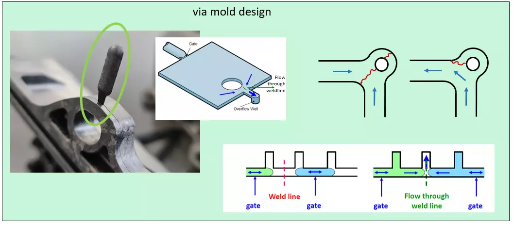
Through-flow
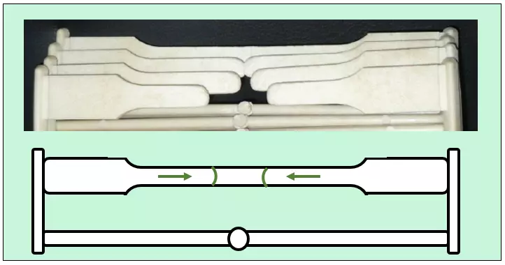
Create through-flow at the weldline location. This can be achieved in various ways:
- Via an overflow (see image): A 'meld-line' is stronger compared to a head-on weldline.
- Via part design: Think about (or simulate) the mold flow in advance. Asymmetry may help to place critical locations away from the weldline.
- Via equipment choice: Multi-component molding (possibly with backflow) or piston-driven SCORIM (Shear Controlled Orientation in Injection Molding) equipment can create a forced through-flow.
Processing Solutions
Even once part design and mold design are fixed, there are still options to improve weldlines. Have a look below for inspiration on troubleshooting or contact one of our experts!
Pressure control
- Optimize the switch-over point to the holding pressure: shortly before the volumetric filling has been reached (approximately 98 % of the filling level ), change over to holding pressure.
- Higher holding pressure (better compensation shrinkage at weldline)
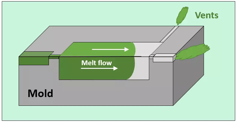
Vents
Venting is essential for injection molded parts, and in particular for the quality of weldlines. If number of vents, their locations and dimensions cannot be changed, it's still important to check if all vents are clean and function as intended.
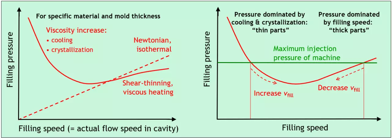
Filling speed
The filling speed is an important parameter for injection molding and is closely correlated to the filling pressure (see graphs on the right).
Improvements with respect to weldlines can often be achieved by increasing the injection speed to avoid early cooling. However, if venting problems are encountered in the area of the weldline, the injection speed should be reduced.
Flow pattern
- Altering the flow pattern can adjust the weldline location to a less critical spot of the part.
- Cascade injection: Using cascade injection (for multipe gates) it's possible to increase the surface area at the weldline location, thus creating a stronger connection between the two melt fronts.
The image on the left shows an example using meltfronts of the same material with and without colorant.
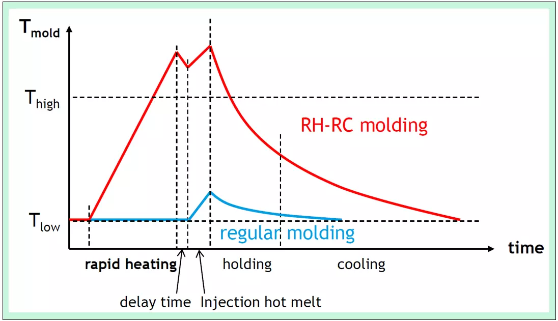
Temperature control
- Increase meld/mold temperature to achieve improved healing.
- Rapid-heat rapid-cool molding: In contrast to regular molding, in RH-RC molding the mold is heated to a higher temperature, which improves the melt flow. After injection, a longer period of cooling is required. This method can improve weldline quality, but takes somewhat longer in processing.